
Automotive Repair & Maintenance / Original EGO R8 guide; Honda maintenance reference / Sep 24, 2026
EGO R8 for Automotive Repair and Maintenance Capture
Plan automotive repair and maintenance recordings with EGO R8: synchronized global-shutter stereo, selectable IMU rates, timestamps and USB capture settings.
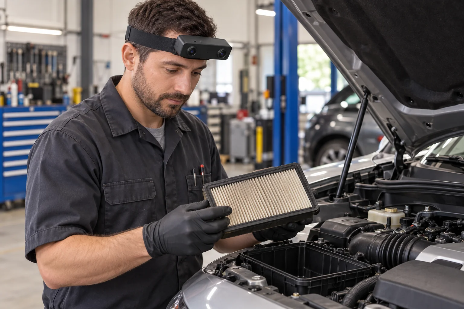
How can R8 support a maintenance recording project?
- Head-mounted stereo views record the technician’s perspective of the service task.
- Dual global-shutter sensors share a common hardware trigger or shutter signal.
- Selectable 100 / 200 / 500 Hz IMU sampling and unified timestamps link visual and inertial records.
- USB capture settings and per-unit calibration data keep each session tied to its R8 configuration.
EGO R8 is a head-mounted USB stereo camera for first-person data collection. In an automotive repair and maintenance recording project, its dual global-shutter cameras, common hardware trigger and synchronized visual-inertial data provide the capture foundation for documenting a technician’s work. This guide uses engine air-filter inspection and replacement as a concrete service-bay example, with the recording organized around what the technician sees and handles.
Define a documented maintenance task
Honda’s official filters guidance identifies engine air-filter inspection and replacement as maintenance tasks governed by the vehicle’s owner’s manual or Maintenance Minder. That documented task supplies the automotive context here. For an R8 recording plan, define the vehicle, service task and relevant manufacturer procedure before capture. An initial view of the working area, the visible filter-handling sequence and a final view of the completed work give the recording a clear beginning, action sequence and endpoint.
Frame the hands and engine-bay working area
Position R8 on the technician’s head and review a short sample from the actual working stance at the open engine bay. Check that both camera views include the hands, filter and working area during inspection and handling. R8’s fixed-focus lens is listed with a 115° horizontal and 80° vertical field of view. These values help define the framing discussion; select the wearing angle and working position by examining the captured images at the distances used for the task.
Record the same action in synchronized stereo
R8 uses dual global-shutter sensors: the pixels in each sensor are exposed simultaneously. In the maintenance sequence, this is relevant when the technician moves the filter through the view or changes head position to inspect the working area. The two cameras also share a common hardware trigger or shutter signal. Preserve the synchronized left and right recordings together so the same handling moment can be reviewed in both views.
Keep head movement on the image timeline
The manufacturer specifies a 6-axis IMU with selectable 100, 200 or 500 Hz sampling and unified timestamps for camera frames and IMU samples. For the R8 head-mounted recording, retain the selected IMU rate with the session settings. The common timeline allows a reviewer to locate the inertial samples associated with a visible head movement or pause during the filter inspection. Camera-frame timestamps, inertial timestamps and the original streams belong together in the recording package.
Select the delivered USB video mode
R8’s main specification table lists 1600 × 1200 at 30 fps and H.264/H.265 output. Its separate USB mode table lists MJPG at 1920 × 1080 and 30 fps, YUY2 at 1920 × 1080 and 15 fps, and both formats at 1280 × 720 or 640 × 480 and 30 fps. Confirm the delivered resolution, format, frame rate and simultaneous stereo-stream configuration against these separate tables. Keep the selected mode in the service-session record so reviewers know which image configuration produced the footage.
Associate the recording with its calibration data
The R8 manufacturer document describes per-unit calibration data: camera intrinsics, distortion coefficients and stereo extrinsics where applicable. Associate the supplied calibration file with the R8 unit and the selected recording mode. For an automotive capture project retaining stereo data for subsequent analysis, this preserves the connection between the image pairs and the relevant camera geometry. Include the device identifier and calibration-file version in the session notes.
Prepare the USB capture connection
R8 uses USB 2.0 and specifies a DC 5 V supply with a maximum working current of 320 mA. Arrange the capture-host connection for the technician’s working position and retain the power and video configuration with the session. SDK/API provision is also listed in the manufacturer document. A project team can discuss the supplied interface and capture settings when planning how its own recording software will collect the R8 streams.
Review and label the visible maintenance sequence
Review the R8 footage around observable maintenance events: the filter presented for inspection, the handling sequence and the final working-area view. A reviewer can add those event labels manually to the image timeline and keep them with the task description and vehicle reference. For each chosen segment, check that the task is visible in the stereo pair and that its camera and IMU records remain associated. This produces an organized first-person recording for the team’s own maintenance-workflow review.
Plan an R8 workshop recording pilot
An R8 automotive recording pilot can therefore be scoped around a specific service task and a defined capture package: paired global-shutter views, the selected USB mode, camera and IMU timestamps, the IMU sampling setting and unit-specific calibration information. Bring that task description and the required recording configuration to the EGO product team when discussing samples and integration. The evaluation can then focus on the actual workshop footage and the documented R8 configuration used to acquire it.
Application reference and R8 specifications
Honda — engine air-filter inspection and replacement guidance